An Unbiased View of Wedge Barriers
Indicators on Wedge Barriers You Should Know
Table of ContentsThe Best Guide To Wedge BarriersGetting My Wedge Barriers To Work

18 might be done much more promptly, easily, and price successfully. FIG. In particular embodiments, the support 30 might be a steel frame consisting of plates, beams(e. g., I-beams ), and/or other frameworks that are safeguarded within the foundation 14, which might be concrete. At the surface area 12, a top side 28 of the support 30 may go to least partly exposed
, consequently enabling the accessory of the obstacle 10 to the support 30. g., threaded holes)in one or more beam of lights or plates of the support 30 might be exposed to the surface 12. In this way, screws 32 or other mechanical fasteners may be utilized to safeguard the barrier 10 to the anchor 30. As the barrier 10 is installed to the surface area 12 of the structure 14, collection of particles and other material below the barrier might be lowered, and parts of the bather 10 may not be exposed to below grade atmospheres. As suggested by referral numeral 52, the lifting mechanism 50 includes elements disposed underneath the wedge plate 16. The components 52 beneath the wedge plate 16 might consist of an electromechanical actuator, a web cam, one or even more web cam surface areas, and so forth. Additionally, the training system 50 consists of a springtime assembly 54
The spring rod 58 is coupled to a cam(e. g., cam 80 received FIG. 4) of the training system 50. The springs 60 disposed regarding the spring rod 58 are held in compression by springtime sustains 62, including more helpful hints a taken care of spring support 64. That is, the set springtime support 64 is taken care of loved one to the structure 14 and the rest of the bather 10.
Wedge Barriers Fundamentals Explained
The remaining force applied to
the cam to deploy the wedge plate 16 may be provided supplied an electromechanical actuator 84 or other various other. The springtime setting up 54 and the actuator 84(e. Wedge Barriers. g., electromechanical actuator)might run with each other to convert the cam and lift the wedge plate 16.
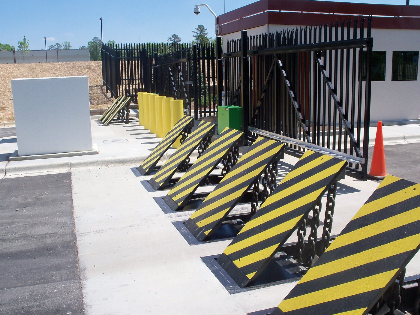
As pointed out over, the springtime setting up 54 puts in a consistent pressure on the camera, while the electromechanical actuator might be regulated to apply a variable pressure on the camera, therefore making it possible for the training and decreasing( i. e., deploying and withdrawing )of the wedge plate 16. In particular personifications, the consistent pressure used by the springtime assembly 54 may be adjustable. g., electromechanical actuator) is disabled. As will certainly be valued, the springtime setting up 54 may be covered and safeguarded from debris or other components by a cover plate(e. g., cover plate 68 received FIG. 4) that might be considerably flush with the raised surface area 38 of the foundation 14. As discussed above, in the released position, the wedge plate 16 offers to obstruct accessibility or traveling beyond the barrier 10. For example, the obstacle 10(e. g., the wedge plate 16 )may block pedestrians or vehicles from accessing a building or path. As discussed over, the barrier 10 find out here is connected to the support 30 protected within the foundation 14,
front brackets 71. As a result, the linkage assemblies 72 may pivot and rotate to enable the collapse and extension of the linkage assemblies 72 during retraction and deployment of the bather 10. The linkage assemblies 72 cause movement of the wedge plate 16 to be limited. If an automobile is taking a trip towards the deployed wedge plate 16(e. For instance, in one condition, the safety and security legs 86 might be expanded throughoutmaintenance of the barrier 10. When the security legs 86 are deployed, the safety legs 86 sustain the weight of the wedge plate 16 versus the surface 12. Because of this, the training system 50 may be deactivated, serviced, gotten rid of, changed, and so forth. FIG. 5 is partial perspective sight of a personification of the surface-mounted wedge-style barrier 10, illustrating the cam 80 and the web cam surface areas 82 of the lifting device 50. Especially, two cam surface areas 82, which are described as lower cam surface areas 83, are placed below the web cam 80. The reduced web cam surfaces 83 might be repaired to the surface area 12 (e. As an example, the lower web cam surfaces 83 and the mounting plate 85 might form a solitary piece that is secured to the support 30 by bolts or various other mechanical fasteners. In addition, two web cam surfaces 82, which are described as upper web cam surface areas 87, are positioned over the web cam 80 and paired to (e. In other personifications, stepping in layers or plates may be positioned in between the surface 12 and the reduced webcam surface areas 83 and/or the wedge plate 16 and the upper camera surfaces 87 As stated above, the camera
80 translates along the camera surfaces 82 when the wedge plate 16 is lifted from the withdrawed position to the released placement. Additionally, as stated above, the spring setting up 54 (see FIG. 3 )might offer a pressure acting on the webcam 80 in the instructions 102 by means of spring rod 58, which might lower the force the electromechanical actuator 84 is needed to use to the cam 80 in order to actuate and raise the wedge plate 16. 1 )to the released placement(see FIG. 4). As shown, the webcam 80 consists of track wheels 104(e. g., rollers), which get in touch with and equate along the web cam surfaces 82 during operation.